Tuesday, August 19, 2008

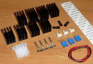
HD 4870 volt mod kits available!

Yep, i've got some things sorted and they're ready to go. There's only a limited quantity for now but depending on the response, i'll try and get a larger range in. Email me if you have a different video card and i might be able to work something out (i should have the bits for GTX280s too).

The kit consists of:
8 x Black Ramsinks (i can provide two lower profile heatsinks if waterblock clearance is an issue).
1 x 50/100ohm Trimpot
2 x 5k Trimpots
3 x 3-pin headers
3 x Jumpers
1 x Molex Connector
Strip of Seksui thermal tape
Hookup wire.


All you need is a multimeter, soldering iron, hot glue or alternate method to attach trimpots, appropriate video card cooling and of course, patience!

Price is $30 delivered anywhere in Australia.

Email me to order. I accept direct deposit (preferred) and paypal.


I accept no responsibility for incorrect use of this kit and any damage you might cause to your video card. All trimpots are fully tested before shipping. My blog is to be used as a guide only. Volt modding voids all manufacturers warranty.

Basic condensation prevention.

Recently there have been many new people getting into sub zero cooling who still aren't quite sure how they should go about insulating a motherboard. I managed to take a few photos when preparing my new DFI board a few weeks ago and decided to whip up this quick little guide to aid anyone new to phase change (or even DICE). This is the method i use for my main rig which has been running for months without problems.

Equipment needed:
- Closed cell foam (ie neoprene). I use 6mm stuff.
- Aerotape. Basically thick, foamy insulating tape (great stuff!)
- Seal string. I hate this stuff, but it's handy.
- Conformal coating/pcb lacquer. To seal the motherboard from the devil (condensation).
- Nail Polish.
- Di-electric grease.
- Wooden skewer.
- Tracing/baking paper.
- Stanley knife.
- A motherboard + cpu is handy too!


Do not attempt to go further if you aren't happy with the fact that you're voiding your warranty. If you mod it and it dies, suck it up and buy a new one.


First step is to TEST THE MOTHERBOARD USING AIR/WATER TO ENSURE IT ISN'T ALREADY BUGGERED! This only applies of course if it's a new motherboard :).

Next, take apart the rig and transport the motherboard outside (fish aren't necessary but do make a nice background).


Now relocate away from the fish and arm yourself with a can of pcb lacquer! Make sure you're outside because last i checked, this isn't good for your lungs (or carpet). Do a couple of light coats, letting it dry inbetween. You only really need to spray behind the cpu socket area, but it's just as easy to spray the entire board. This will seal off the PCB so if any condensation does form, it can't really do anything.


Now we have the backside protected, it's time to attack the socket. To do this, we're going to whip out the nail polish. The idea is to 'paint' around the socket to protect the pcb and components much the same and the pcb lacquer on the backside. Don't be shy with this stuff, the more the merrier! Just make sure you don't get any in the cpu socket or else you've got one gnarly looking paperweight (i like to put the socket protector that comes with the mobo back in the prevent any accidents).


Grab your foam, measure the cpu socket area and mark it out. I normally use foam in a square using the edge as one side, ram slots as the second, northbridge as the third and then the mosfets as the last edge. This should be plenty unless you're going LN2 (which won't be 24/7 anyway).


Now we get out our pencil and tracing paper (baking paper works great too). Push the paper down over the cpu socket and surrounding components and trace with the pencil where everything is. Now we cut out the stencil and then transfer it to our square of foam. I don't have any pictures of this step because the DFI board i was using had nothing around the cpu socket! Excellent board to work with!

Here's a picture with the cpu socket cut out already. Pretty sloppy, but i don't really care all that much to be honest. Notice there's only two cut-outs required. One for the CPU fan and one for a capacitor.


If you haven't worked out yet, the stanley knife is bloody useful cutting this stuff (or any knife really, good luck with scissors!). For the capacitor hole, i just pierced it with a wooden skewer (the ones you might penetrate meat with to make a kebab) and then stuck a pen through the hole to make it a little bigger. This should give it just enough slack to get over the cap and form a tight seal.


Now we check that it all fits... Huzah!


Now throw the cpu in there and drop the socket lever down. It's also a good idea to put some di-electric grease under the cpu before installing. Use seal string on any suspect areas that you think might not be air-tight.


Now build up around the cpu with the Aerotape. You could also use another thin layer of neoprene, but aerotape is the shit.


Find you backing plate and cut a suitible sized square of foam for the back of the motherboard (usually the same size as the plate). Now use the wooden skewer again to penetrate through the insulation that is covering the 4 motherboard mounting holes (push through from the back... obvious to some, but you never know). Now push the 4 bolts through and check the back plate is pushed evenly against the motherboard.


Now mount that sucker! Tighten the bolts in the classic 'cross pattern'.


After mounting, loosen the bolts and check that a) your mount was even and b) there was no foam/aerotape getting between the cpu and the evap. If it's all good, re-mount and fire it up!

Wednesday, August 6, 2008

Overclocking the HD4870 in CF

Due to some cpu/motherboard problems i haven't had too much time to test these suckers properly. Unfortunately after forking out for a shiny new E8600, i've hit a wall at 4.75ghz where it is 100% prime stable at 1.4v but it won't even load windows at 4.8ghz regardless of voltage. I'm currently pointing the finger at my new DFI X48-T3RS for that little problem, but from what i've read these boards have no problem going over 475fsb. Not real happy so the results are limited to the old testing i did on my Gigabyte X48-DS4.

Test pad:
E8400 @ 4ghz (or maybe 3ghz?)
Gigabyte X48-DS4
Corsair Dominators @ 1066mhz 5-5-5-12
2 x HD4870 volt modded and watercooled
74gb Raptor
Corsair HX-1000
Everyday, bogged down Vista Ultimate 64bit install


Now it's time to play. Here's a shot of the cards in action. I know, it's a beautiful site and probably needs a NSFW warning :lol:.


The first 4870 i tested maxed out at 950mhz at ~1.4v on water. I had never tested the second 4870 so i wasn't sure what to expect when overclocking them in crossfire so i was hoping to match these clocks.

Testing was done using 3Dmark Vantage. I know there's plenty of people out there who don't like Vantage but FFS, i paid $$$ for this so i'm going to milk it until it dies!

I bumped the volts straight up to 1.4v and tested at 900mhz... pass! Huzah! That's respectful enough, but i wanted more. I then raised the clock speed up to 930mhz... again, pass! Still no artifacts or any signs of instability. Things were starting to look good for 950mhz, so i did just that. Set the clocks to 950mhz and ran Vantage. *crash* Oh well, she didn't quite make it. I managed to pass at 941mhz artifact free which is still a pretty extreme clock. Unforunately, much like when in single configuration, anything over 1.4v didn't help. I'd love to get some DICE on to these things but i can't forsee any money coming my way that i can justify to use on two copper pots.

Here's a screenie


Disregard the poor score, it's not exactly a tweaked os installation atm.

I've also since flashed these cards to the Diamond XOC bios which allows overclocking in CCC up to 990/1200. This should be plenty of headroom for all you extreme overclockers. Stock speeds are 800/1100 but i've edited them to 820/1000 for 24/7 use. I might post a quick guide later to flashing your bios, but there's plenty of resources out there for this.

Saturday, August 2, 2008

Yes, they're coming!

Just waiting to find some time to insulate my new motherboard... Then we will see what the 4870 can really do!

Wednesday, July 30, 2008

Volt modding the HD4870.

Ok, here we go. Time to mod the 4870.

The tools we need:
- Digital Multimeter. Do not perform any kind of volt mods without one of these.
- A low wattage soldering iron. A 15watt dick smith/jaycar cheapie will do the job. Make sure it has a nice sharp tip, otherwise it can get difficult in tight places.
- Some kind of wire cutters/strippers to make life a little easier.
- Small wire. Solid core is better for this stuff imho. I usually cut IDE cables into strips and use them. Perfect size for volt modding.
- A hot glue gun/double sided tape or alternative solution to mount components to pcb.
- Electrical tape (optional)
- 1 x 50ohm trimpot. Used for adjusting gpu voltage. 100ohm is also suitable.
- 2 x 5k multiturn trimpots. Used for adjusting DDR voltage.
- 3 x 3pin fan headers - used for turning the mods on/off.
- 3 x jumpers from an old motherboard/hard drive. used with the 3pin header for on/off control.
- 1 x Molex connector for checking voltages

Now you've got the tools, lets get on with the job.

Here's an overview of the card showing the areas we will be working in and the required voltage reading points. For the MVDDC and MVDDQ read points, you can use any of the points in the highlighted area.


Continuing on with the same techniques as used on the 4850, we will sandwich a trimmer between the pcb and a 3pin fan header. Cut off the pin on the left hand side of the trimmer. Bend the middle leg of the trimmer up towards the middle leg of the fan header and solder them together. Now turn the trimpot all the way to the left (raise resistance, lower volts) and check that the resistance between the two remaining legs on the trimpot is 50ohm (maximum). Now solder a wire to the remaining leg of the trimpot. This leg will be soldered to the pcb.


Sorry about the cruddy picture, but i forgot to take a shot of the card with the sticker removed. Here's a shot with the wire already soldered on. It's not the best photo but there isn't much going on around it so you shouldn't have too much trouble working out where it goes. The pad that you solder to is quite small here, some people like to add a drop of hotglue to add extra strength to the connection. I trust my soldering.


Now lay the sticker gently back over the mod. I guess since we haven't removed it, our warranty should be all good... riiiight? Ok, bad joke. Just like the 4850, i put some electrical tape over the wire to prevent it getting caught on anything while handling.


Here's where you have two options. a) Give each mod it's own ground or b) use the same ground point for all mods. I will continue the guide using a mix of both... for extra confusion :).

I use the PCI-E connector as the ground. It's close and very easy to solder to. Before continuing, double check that the resistance is still set at 50ohms! We wouldn't want to boot up and have a dead card would we?


Memory time!
Hopefully this one should be a little easier since i had a nice photo of this area. The green points are where to solder the remaining leg of the trimpot to. I have highlighted two ground points in yellow. You can either use serperate grounds here or share one between the two. On this card, i shared the top one.


Memory VDDC installed.


Now with the VDDQ installed. Notice how i have soldered the ground wire for this mod to the ground on the MVDDC? This is no advantage/disadvantage to doing this. It just reduces pcb soldering and potential problems. Again, double check that all the trimpots have their resistance set at full!


Here is a close-up of the soldering.


Now get that molex out and start wiring up the reading points! Try not to short connections when soldering to the (somewhat cramped) MVDDC and MVDDQ read points. The VGPU read point will be like a holiday :).
This picture also shows how to use method 'b' as explained earlier. Here you can see that all the ground points have been connected together and go to the one ground (the PCI-E connector). I like this method because it makes things a little bit easier and neater.


And we're all done!
Here's a few pictures of the completed mods :)


Now just add your ramsinks and waterblock of choice and overclock away!


One last note, don't forget to sink the voltage regulators. I haven't done so yet because i had trouble getting anything to stick with thermal tape and i've run out of arctic ahesive. This is a must because they get hot and you certainly don't want one of them to fry. I need to fix this asap so i'll have a go a modding something on the weekend. Should have a guide up soon after!


Recommended VGPU voltages:
Stock - 1.28v
Air - 1.35v max
Water - 1.4v (i saw no increase in mhz after 1.4v. I'd love to know if you get results above this)
DI/LN2 - Who knows, just keep going up :D


Enjoy safe (but extreme) voltage.