Wednesday, July 30, 2008

Volt modding the HD4870.

Ok, here we go. Time to mod the 4870.

The tools we need:
- Digital Multimeter. Do not perform any kind of volt mods without one of these.
- A low wattage soldering iron. A 15watt dick smith/jaycar cheapie will do the job. Make sure it has a nice sharp tip, otherwise it can get difficult in tight places.
- Some kind of wire cutters/strippers to make life a little easier.
- Small wire. Solid core is better for this stuff imho. I usually cut IDE cables into strips and use them. Perfect size for volt modding.
- A hot glue gun/double sided tape or alternative solution to mount components to pcb.
- Electrical tape (optional)
- 1 x 50ohm trimpot. Used for adjusting gpu voltage. 100ohm is also suitable.
- 2 x 5k multiturn trimpots. Used for adjusting DDR voltage.
- 3 x 3pin fan headers - used for turning the mods on/off.
- 3 x jumpers from an old motherboard/hard drive. used with the 3pin header for on/off control.
- 1 x Molex connector for checking voltages

Now you've got the tools, lets get on with the job.

Here's an overview of the card showing the areas we will be working in and the required voltage reading points. For the MVDDC and MVDDQ read points, you can use any of the points in the highlighted area.


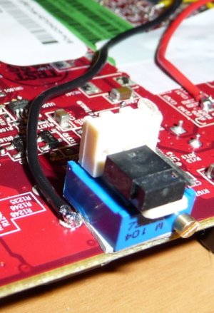
Continuing on with the same techniques as used on the 4850, we will sandwich a trimmer between the pcb and a 3pin fan header. Cut off the pin on the left hand side of the trimmer. Bend the middle leg of the trimmer up towards the middle leg of the fan header and solder them together. Now turn the trimpot all the way to the left (raise resistance, lower volts) and check that the resistance between the two remaining legs on the trimpot is 50ohm (maximum). Now solder a wire to the remaining leg of the trimpot. This leg will be soldered to the pcb.


Sorry about the cruddy picture, but i forgot to take a shot of the card with the sticker removed. Here's a shot with the wire already soldered on. It's not the best photo but there isn't much going on around it so you shouldn't have too much trouble working out where it goes. The pad that you solder to is quite small here, some people like to add a drop of hotglue to add extra strength to the connection. I trust my soldering.


Now lay the sticker gently back over the mod. I guess since we haven't removed it, our warranty should be all good... riiiight? Ok, bad joke. Just like the 4850, i put some electrical tape over the wire to prevent it getting caught on anything while handling.


Here's where you have two options. a) Give each mod it's own ground or b) use the same ground point for all mods. I will continue the guide using a mix of both... for extra confusion :).

I use the PCI-E connector as the ground. It's close and very easy to solder to. Before continuing, double check that the resistance is still set at 50ohms! We wouldn't want to boot up and have a dead card would we?


Memory time!
Hopefully this one should be a little easier since i had a nice photo of this area. The green points are where to solder the remaining leg of the trimpot to. I have highlighted two ground points in yellow. You can either use serperate grounds here or share one between the two. On this card, i shared the top one.


Memory VDDC installed.


Now with the VDDQ installed. Notice how i have soldered the ground wire for this mod to the ground on the MVDDC? This is no advantage/disadvantage to doing this. It just reduces pcb soldering and potential problems. Again, double check that all the trimpots have their resistance set at full!


Here is a close-up of the soldering.


Now get that molex out and start wiring up the reading points! Try not to short connections when soldering to the (somewhat cramped) MVDDC and MVDDQ read points. The VGPU read point will be like a holiday :).
This picture also shows how to use method 'b' as explained earlier. Here you can see that all the ground points have been connected together and go to the one ground (the PCI-E connector). I like this method because it makes things a little bit easier and neater.


And we're all done!
Here's a few pictures of the completed mods :)


Now just add your ramsinks and waterblock of choice and overclock away!


One last note, don't forget to sink the voltage regulators. I haven't done so yet because i had trouble getting anything to stick with thermal tape and i've run out of arctic ahesive. This is a must because they get hot and you certainly don't want one of them to fry. I need to fix this asap so i'll have a go a modding something on the weekend. Should have a guide up soon after!


Recommended VGPU voltages:
Stock - 1.28v
Air - 1.35v max
Water - 1.4v (i saw no increase in mhz after 1.4v. I'd love to know if you get results above this)
DI/LN2 - Who knows, just keep going up :D


Enjoy safe (but extreme) voltage.

Friday, July 25, 2008

HD4850 + Thermalright V2 (now with extra volts!)

I decided to quickly do some testing with extra volts before i retire this card.

I bumped the gpu up to 1.33v and went for gold. I managed stable clocks (3dmark, crysis, cod4) at 850mhz on the core. This was only 40mhz lower than with watercooling at the same voltage. Temps only just hit the sixties (full load) even with such high clocks and overvolted. This really says something about the quality of the heatsink.

Anyway, here's the usual screenie to justify my rambling above.


I'd recommend this little bugger for anyone who wants to do some overclocking on the cheap.

Thursday, July 24, 2008

Mini Review: Thermalright V2 VGA Cooler (on a HD4850!)

After butchering the heat sink on my poor old HD4850 with an angle grinder (long story...), i needed a new, cheap and effective way of cooling this card. After browsing through the usual online stores, i stumbles across the Thermalright V2 copper heat sink at PCCG for $27. Considering most (ie more recent) coolers were around the $60 mark, i thought it looked like a great little buy. I didn't need maximum performance, just something to replace the already lacking stock cooler.

Here's a shot of the typical Thermalright packaging. Plain old cardboard. Just the way i like it, no rice, just performance!


Here's the bundle of goodies hidden away inside. We have the heat sink, instructions, ram sinks (hah, if you can call them that!), thermal paste, mounting hardware and of course, the trademark crappy Thermalright sticker!


Here's a closer look at the heat sink. Pretty standard all copper design with 4 heatpipes. Nothing new here, it just looks like a low profile version of the old XP-90C.


A shot of the base. A little bit grubby, doesn't bother me all that much. All the people that require A++ mirror finishes from the factory will not be impressed though.


Ahh the 'ram sinks'...... Just look at the size of this thing. IT'S ONLY JUST BIGGER THAN A BLOODY FAN CONNECTOR. I think it might hinder performance if anything, but it was free... so it goes on!


Here's a shot with the ram sinks installed. You might notice there's two which are almost flat. This is because the heatpipes won't fit over the standard sized sinks. Again, it probably just heats the ram more. You might want to consider some kind of mosfet cooling at this point. You can see my heatsink which i used earlier with my watercooling.


The heatsink is mounted with 4 thumb screws on the back. Installation was very quick and easy. No crushed cores today *remembers mounting volcano 7's on 9700 cards*


Here's a shot of it installed. One positive of this heat sink is it's fairly low profile. There's plenty of room if you're running a crossfire/sli setup.


Now with a 80mm fan installed. This little Spire fan has been going strong for years!


Now to performance... I wasn't sure what to expect here as I'm very unfamiliar with any gpu heat sinks made in the last few years. I bought this on clearance so i wasn't going to rule out average/poor performance with such a new and toasty card.

The results? Great! Idle temps were down to 31 degrees where the stock hsf would hover around in the 60s. Under full load, temps only reached an amazing 44 degrees! This was an amazing 36 degrees lower under load than the stock heatsink! For $27 i was absolutely over the moon with the performance, not to mention almost dead silent operation.

So... the overclocking! I managed to reach 700mhz on the core with this cooler. That's a 33mhz improvement over the stock cooling. After overclocking max temps only reached 47 degrees under load. Again, i was very impressed with this result. I feel that the overclock was purely voltage limited after seeing how well it flew with extra volts under water. I'm not going to over volt it under air atm because this card is soon to be retired and hopefully going to a new loving home where the owner will overclock the s*** out of it!

Tuesday, July 22, 2008

Overclocking the HD4870 and GTX280

Ok, it's time post up some of my initial overclocking results done under stock air cooling. Both were done in a nice and toasty room with the heater on. Naturally this isn't very overclocker friendly but it sure beats hypothermia.

Test Rig:
E8400 @ 4000mhz (445x9)
Gigabyte X48-DS4
Corsair Dominator 2x2gb @ 1066mhz 5-5-5-12
Palit GTX280
Connect3D HD4870
WD 74gb Raptor
Corsair HX-1000
Windows Vista Ultimate 64-bit

First up is the 4870. With the previous excitement over the 4850, i just couldn't help myself and cracked open the box faster than you can do something fast... (err?).

The stock cooler on the 4870 is a dual slot hsf which exhausts heat outside of the case. It performs decently enough and is not audible over my SS phase unit... but that's not very hard! Actually it's extremely quite during general use and even while gaming. Fortunately it does not have that annoying whirrr sound that so many crappy little vga fans have. Under the plastic over is a lovely little copper based heatsink with two heatpipes. Here's a picture of the naked heatsink mounted on my HD4850.


Excellent, now that boring crap is out of the way, it's time to overclockzor (yes i just said overclockzor). Here's a tasty picture to wet your appetite.


I was able to acheive some decent clocks using air cooling. I used Crysis and 3DMark Vantage to test stability and i managed to get a clock speed of 850mhz on the core. I managed a suicide run at 870mhz but i got slight artifiacting in some spots. Here's a screenie of Vantage at 850/900.

I didn't overclock the memory at this stage because we all know how silly the idea of air cooling is...


Ok, enough of the red stuff. Time for the GTX280 goodness.

I managed to pick this baby up at $540 which i thought was a decent price. I originally tried to stay away from the GT200 series of cards, but with the massive price drops i couldn't resist.

There was one thing that came to mind after unpacking the GTX280... HOLY FUCK SHE'S A BIG ONE. Yep, she's a big one. I had to hire a crane just to load up to the test bench. But you don't buy this card if you worry about those things. This card was designed to double your electricity bill, help you bulk up, compensate for a small willy and i guess speed too. Enough taking the piss, here's a picture of it next to my PSU box (yes, i know the HX1000 is shit hot but please, look at the video card).


And now a shot of her crunching away. This thing is big, mean and intimidating. Do not leave your PC unattended if you have children, i hear they double as grizzly bears.


As you can see, the GTX280 uses 1x6pin PCI-E and 1x8pin PCI-E. It seems like something silly to point out but there are plenty of angry new GTX280 owners out there who can't use their cards yet because most companies are too tightarse to include a molex to 8pin coverter. So remember kids, make sure your PSU has at least 1x6pin and 1x8pin connectors or pre-purchase a molex to 8 pin coverter!

Now we have that out of the way and i've run out of lame nvidia bashing jokes, it's time to start overclocking. The program i used to overclock this card was the EVGA Precision overclocking tool. Yes i'm aware i'm using a Palit card, not EVGA, but this tool is great! I've never liked the very popular Rivatuner because frankly, it's just full of crap i just don't care about. I want to overclock, maybe check temps sometimes... that's it! Evga Precision is super straight forward - OC core/OC Shader/OC Memory and temp display. The GUI is very easy on the eyes too. Infact, i like it so much i'm even going to share a picture!


Ok, hopefully you've cleaned up and cleared your desk of any tissues so we can continue.

Unfortunately being limited to stock air cooling and having a card with an already monster-like heat output, we were never going to have much overclocking headroom. I managed to get a meazly 80mhz overclock from the gpu. Even then, i noticed some slight (very slight) artifacting sometimes during Vantage. This doesn't fill me with much confidence for the card after seeing the HD4870 easily hit 100mhz on the core. However all hope is not lost, after some decent cooling (i hope the mcw60 fits over the massive gpu) and volt mods, anything is possible. Here's a screenshot of a Vantage run at 680/1100 (stock mem). I managed to break 10k here which was pretty amazing for such a modest overclock on the video card and cpu.


Another thing to note is the smoothness that the GTX280 seems to have. The extra power just manages to break the struggle that the HD4870 experienced in Vantage and Crysis. Maybe it was all in my head (trying to justify $540), but i could definitely feel that extra oomph there.

Overall i was impressed and disappointed with the way these cards performed on air. The GTX280 is Nvidias current flagship cards and although it's a monster in its own right, i expected more overclocking headroom to be there. The HD4870 made me feel like there's just needs to be a little more there, but for $300, it's a bloody steal. Thankfully ATi have brought back some seriously ass kicking cards (R300 again anyone?) and have forced nvidia to dramatically restructure their pricing. I remember not too long ago buying the X800XTPE for nearly $900 which was more than i paid for both the GTX280 and HD4870. In conclusion.. BUY BOTH (so you can overclock and kill one of them - it's fun).

Lastly...
Here's a little teaser of what's to come next time...


Yep, and it isn't even modded yet...

Saturday, July 19, 2008

Unleashing the 4850 Part 3 - Cooling and overclocking

Finally i will finish off my little HD4850 adventure. I was quick to wrap this up because i picked up some new hardware today and just couldn't wait to play.

Here's the naked card. We will need to add a heatsink to the mosfets on the right which is very important because these suckers get hot.


Here's the heatsink in question. I found it in the deep dark depths of my cupboard o' crap. I think it was an old P3 heatsink (half of one anyway).


Here's a shot of the bottom. The small step makes it a perfect fit for the card!


I installed it using thermal tape but due to its weight, i used a cable tie to ensure it doesn't fall off.


I had every intention of adding ramsinks, but unfortunately i didn't have any on hand that were suitable. The best ramsinks (imho) are made by chopping up any old gpu/cpu/nb/sb heatsinks and sticking them on with artic adhesive or thermal tape. Spending $30 for a pack of 8 pre made ramsinks is crazy. I know i can think of hundreds of better things to spend that on. Do not overvolt the ram without ram sinks. The ram gets very hot to touch even at stock settings, i do recommend overvolting with ramsinks and decent airflow.

I'll be using a Swiftech MCW60 waterblock to cool the gpu on this beast. Many prefer the option of the full cover waterblocks but nothing can match the simplicity and upgradability of the MCW60. I could argue all day why the full cover blocks are a waste of money... but i wont. Lets just get into some overclocking!

Unfotunately nearly all the pictures i took did not turn out. Photography isn't my strongest asset and most shots were taken over by the flash reflection. Here's one shot of the card in my rig with the waterblock installed. One thing to note is how simple reading the voltages becomes with the use of the molex connector. The test probe slots right in and there's no danger of shorting any components. As you can see, the VGPU mod is turned on (bottom) and the VDDR is in the off position.


The test setup:
E8400 @ 4ghz - Frozen SS
Gigabyte x48-DS4
Corsair 2x2gb PC2-8400 Dominators
Connect3D HD4850 - MCW60
74gb WD Raptor
Thermaltake 750watt Toughpower
Fluke Multimeter :)

I used 3DMark Vantage to test for max stable clocks without artifacts. Note that i only overclocked the memory to an even 1000mhz (stock 993mhz). This was due to not having any ramsinks installed and i didn't want to take the risk of damage.

Stock cooling and voltage (1.2v load) i only managed a pathetic 670mhz on the core. Any higher than this and i would get slight graphic corruption and experience crashing. Temps were well above 90 degrees load.

With a voltage bump (1.3v load) i was able to achieve a very respectable 890mhz on the core. I was very happy with this result for safe 24/7 gaming. Temperatures only hit around 43 degrees load which says excellent things about the MCW60.

I finally bumped the voltage again up to 1.4v (still, fairly safe under water) and managed an amazing run of Vantage at 975mhz on the core. This was not stable for 24/7 use however, but with a little extra voltage i'm sure i could have broken 1 ghz on the gpu.


Overall i'm extremely impressed with the 4850s performance and it's excellent response to voltage. Priced at only $200, these cards deliver exceptional results and are unmatchable in their price bracket. I would highly recommend voltmods for this card if you're after maximum performance and are keen to take the plunge into extreme overclocking territory.

More fun to come...

So... i went to buy a new case today and came back with these two beasts.
GTX280 and a HD4870. The HD4850 is there for size comparison.

I expect good times :)

Saturday, July 12, 2008

Unleashing the 4850 Part 2 - Volt Modding

Now we're getting to the fun stuff. Volt modding is great way to get a cheap (free) jump in mhz. Often people are turned away by the thought of potentially damaging the gpu or reducing the life of the video card. In reality it is no different to overclocking and raising the vcore on a cpu. By raising the voltage in small increments and using the appropriate cooling, volt modding is perfectly safe and a great way to either truly push your video card to it's limits or just add some extra gaming performance.

You will need:
- Digital Multimeter. Do not perform any kind of volt mods without one of these.
- A low wattage soldering iron. A 15watt dick smith/jaycar cheapie will do the job. Make sure it has a nice sharp tip, otherwise it can get difficult in tight places.
- Some kind of wire cutters/strippers to make life a little easier.
- Small guage wire. Solid core is better for this stuff imho. I usually cut IDE cables into strips and use them. Perfect size for volt modding.
- A hot glue gun/double sided tape or alternative solution to mount components to pcb.
- Electrical tape (optional)
- 2 x 100k multiturn trimpots. Vertical or Horizontal. Used for adjusting voltage.
- 2 x 3pin fan headers - used for turning the mods on/off.
- 2 x jumpers from an old motherboard/hard drive. used with the 3pin header for on/off control.
- 1 x Molex connector for checking voltages


Now lets get started!

First up are the areas where the work needs to be done. Print these off before you take the video card out of your machine :).

This picture was borrowed from techpowerup. I didn't have a full shot of the rear yet.

VGPU - Solder 100k trimmer between this point and one of the grounds above.


VDDR - Solder a 100k trimpot between these two points.


Here's a picture of the VDDR mod completed. This enables you to raise the voltage to the RAM allowing extra memory speeds. Ramsinks are recommended when using this mod. I forgot to take pictures of the process but it is explained below in more detail for the VGPU mod.
I like to use regular 3pin fan headers combined with a standard motherboard jumper to turn the mod on/off. I have used this method for years and it's very effective if you do not want to run overclocked and overvoltage settings 24/7.

Click for Hi-Res version

Now we will move on to modding the GPU voltage (often reffered to as VGPU).
Here we are using a 100k trimpot. Either horizontal or vertical will work fine - i used vertical ones because that's what i had on hand :).
Here i have used double sided thermal tape to attach the trimmer to the pcb. I prefer using a small dab of hot glue but i wasn't able to locate the gun. I recommend cutting off the 3rd leg of the trimmer which is not required.

Click for Hi-Res version

Here is the trimmer attached to the pcb. Alway try to place it in a practical place which requires the least amount of wiring. Having them at the top edge of the pcb allows for easy adjustment and almost completely reduces the chance of shorting out components when rasing/lowering voltage.

Click for Hi-Res version

Like the VDDR mod, i like to use 3pin fan headers with jumpers to turn my mods on and off.

Click for Hi-Res version

I attached the fan header to the trimmer using more double sided tape. Again, i would recommend using a hot glue gun if you can stand the mess.
Here i have bent the middle pin of the trimmer up and soldered it to the middle pin of the fan header.

Click for Hi-Res version

Next we solder the pin from the fan header to ground. The other pin remains unused and you can remove it if you wish.

Click for Hi-Res version

Now attach a wire to the remaining leg of the trimmer ready to solder to the pcb. Remember to use heatshrink tubing over the connection to prevent any unwanted accidents.
Note: Don't use a lighter to shrink the tubing - cloth covered wire is quite flammable! I also managed to burn the wire. Poor form all-round.

Click for Hi-Res version

Lets solder the yellow wire to the pcb. Make sure you have a nice fine point on your soldering iron for this job, especially if you're new to soldering. The chisel point on my weller made it extremely difficult to do this. Remember - use the right tool for the job! Use some electrical tape as a bit of extra security to hold down the wire to the pcb to prevent it accidently catching on your finger while re-installing the cooler.

Click for Hi-Res version

Here's a picture of the VDDR and VGPU mods completed (and in the off position).
Hmm but how do we measure the voltage?

Click for Hi-Res version

Molex connectors are perfect for the job! Great size for a multimeter lead to sit safely inside. I used two test points on this one - one for VGPU and one for VDDR. It's generally a good idea to add another read point for GND, but it slipped my mind at the time.

Click for Hi-Res version

Here's a shot of the two read points. VDDR left and VGPU right.

Click for Hi-Res version

Here's a shot of all the mods completed.

Click for Hi-Res version


Next up i'll cover installing a waterblock and cooling the ram/mosfets.